Quick Answer
Engine wiring connector differences can help distinguish engine versions, but a single plug is not enough for final identification. Buyers should photograph connector faces, wire direction, sensor locations and the surrounding engine structure. Combine these images with the engine code, transmission, drivetrain and full original-engine views before requesting a quotation.
Why Can Connector Layout Help Identify an Engine Version?
Engines sharing a family name or similar exterior shape may use different sensors, harness branches or connector positions. These differences can relate to production versions, control systems, transmission interfaces or surrounding vehicle equipment. A connector photo therefore works best as one clue within a larger identification record.
Start with the engine code identification guide, then use connector and sensor photos to compare visible version details. Do not cut, adapt or assume interchangeability from appearance alone.
Which Connector Details Should Buyers Photograph?
| Photo | What it should show | Why it helps |
|---|---|---|
| Connector face | Shape, keying and visible terminal arrangement | Supports plug-shape comparison |
| Side view | Locking tab, body depth and wire exit direction | Distinguishes similar front views |
| Location view | Connector beside the sensor and nearby engine structure | Shows where the plug belongs |
| Harness overview | Branch direction, clips and routing around the engine | Supports complete layout comparison |
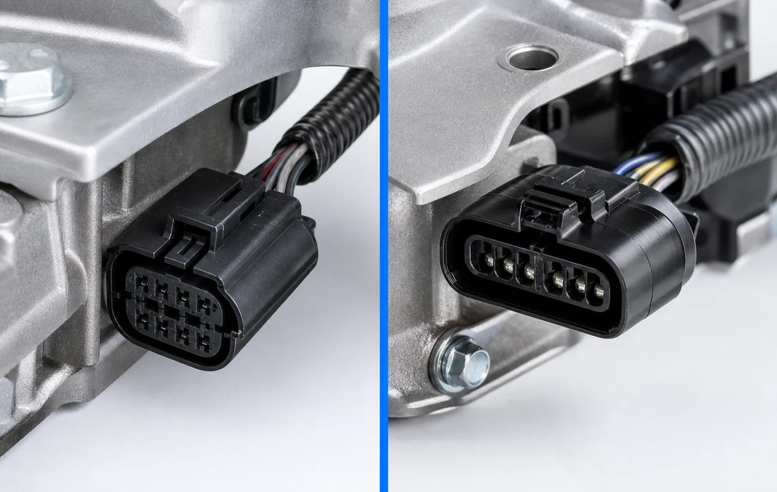
Do Not Compare the Connector in Isolation
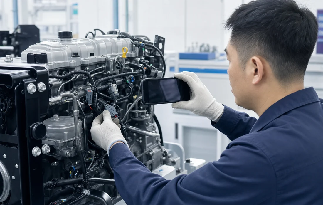
A loose plug photographed against an empty background loses its positional context. Include one close view and one wider view showing the sensor, bracket, cover or casting around it. Keep the connector clean enough to see its form, but do not alter the original wiring just to create a photo.
Top-side components can also provide version clues. Compare connector observations with the valve cover version guide and other visible engine features rather than relying on one detail.
Which Areas Deserve a Complete Photo Set?
- Main harness connection points visible on the engine.
- Camshaft, crankshaft and other visible sensor positions where accessible.
- Throttle, intake-side and fuel-system connection areas without claiming included scope.
- Transmission-side connectors and the surrounding bellhousing interface.
- Damaged, repaired or missing plugs that may affect the inquiry.
Transmission information should be recorded separately because connector and interface details may differ. Review the transmission configuration check before sending the inquiry.
A Repeatable Connector Photo Workflow
- Take a full-engine view: establish which side and area will be documented.
- Take a location view: show the connector together with the nearby engine structure.
- Take a face view: photograph the plug squarely without forcing or disconnecting unsafe components.
- Take a side view: include the locking tab and wire exit direction.
- Label the photo sequence: use simple location names rather than guessing sensor functions.
- Send configuration data: attach the engine code, transmission, drivetrain and original-engine overview.
What Can Connector Photos Confirm—and What Can They Not Confirm?
They can support
Visual comparison of plug shape, sensor position, harness direction and nearby mounting details.
They cannot prove alone
Final compatibility, electrical function, control-system matching or the included scope of an offered engine.
Frequently Asked Questions
Can two connectors look similar but fit different engine versions?
Yes. Similar shape does not establish identical wiring, pin function, sensor specification or control-system compatibility. Compare the wider configuration record.
Should buyers disconnect every plug for photos?
No. Only disconnect components when it is safe and appropriate. Clear location and side views may provide useful evidence without disturbing the original harness.
Does a missing connector mean the engine is incomplete?
Not necessarily. Harness and external-component scope varies by product form and specific offer. Ask the supplier to describe the included scope in writing.
Are connector photos more important than the engine code?
They serve different purposes. The engine code provides an identification foundation, while connector photos can help distinguish visible version details.
Send the Full Engine and Connector Photo Set
Include the engine code, full original-engine views, connector location photos, transmission, drivetrain and required product form. NANXI POWER can use the available information for preliminary quotation review.
View product and technical videos on the official NANXI POWER YouTube.